There are five steps with which you can define a tailored preform design for your application:
1. The right core material for your application
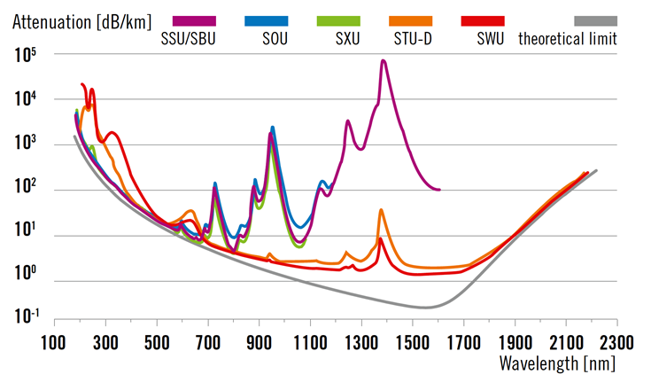
The core material defines the absorption within the final fiber. Therefore, the first step is to choose the right core material depending on the wavelength you want to use. Beside the operational wavelength other conditions like radiation hardness, low solarization or cost targets can determine the best solution for you.

Wavelength range
Low solarization
Radiation resistant
Cost sensitive
Type
Comment
UV 185 - 580
•
SSU / SSS
UV 185 - 580
•
SBU / SBS
UV 308
SXU / SXS
Optimized for 308 mm
UV 190 - 580
•
SOU / SOS
UV - IR 300 - 2,200
•
STU-D / STS-D
IR 700 - 2,200
SWU / SWS
2. Define the optimum guiding layer thickness
To guide the light in your fiber, as rule of thumb the fluorine doped cladding layer with a lower refractive index should have ten times the wavelength you want to operate in the final fiber. If the layer is thinner, you will face guiding losses. The ratio of fiber outer diameter to core diameter is called the Clad to Core Diameter Ratio (CCDR) and is an important parameter describing a fiber design. Keep the fluorine doped layer thickness at a minimum to guide your light. Excess layer thickness will impact your fiber cost.
3. Tailor the guiding properties with the numerical aperture
For the fiber guiding properties, the numerical aperture (NA) is another key element. The numerical aperture describes the acceptance angle of your fiber and the angle of total internal reflection in your fiber. The fiber NA should match with the NA of your light source.
Our standard NA is 0.22 which is common in the fiber world. We can adjust the NA to your needs up to 0.3 with an all-silica fiber.
Type
NA
NA
Standard
0.22 ± 0.02
H
High
0.26 ± 0.02
SH
Super High
>> 0.26
L
Low
< 0.2
Fiber bending influences the NA of a fiber by changing the conditions of the total internal reflection and mechanical stress which influences the refractive index profile. A higher NA can help avoid bending losses when the fiber needs to be bent tightly.
4. Optimize the beam profile with an adjusted core shape
A standard round fiber with a round core area will have a Gaussian beam profile with the highest intensity in the center and the lowest at the outer edges. If you need a homogeneous beam profile, a shaped core could be a solution because a non-circular shape causes mode mixing in multimode fibers. This transforms the Gaussian profile into a homogeneous top-hat profile. A shaped core region could also help you match your core cross-section to the cross-section of your light source.
5. Guide the light in different areas as you need
Light can be guided not only in a central core but also in different areas of the fiber through the application of multiple layers. For instance, one can use a ring instead of the core or direct the light in opposite directions or wavelengths in different areas. In designing optical fibers, only a layer with a lower refractive index is required between the different guiding regions. We support you with our flexible processes in the implementation of even complex fiber designs.

